![]()
- Introduction
- Consortium
- Description
- 3D Mapping
![]()
The TeleRescuer mobile robot was designed based on the project requirements. The robot consists of the main chassis with four independent tracked arms (motors, motor controllers, batteries and the main control system are placed in a flameproof housing), a sensory arm with a sensory head, a 3D laser scanner unit and a mote deploying subsystem (motes are small Wi-Fi repeater mod-ules). Every subsystem has its own independent power supply.
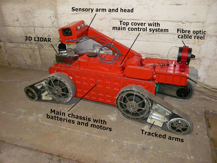
TeleRescuer mobile robot subsystems
The main robot chassis contains the motion subsystem, the main control system (MSC), the communication subsystem and power supply.
The motion subsystem is based on four identical independent flipper arms with tracks. Motors revolutions are reduced by two types of gearboxes: a worm gear and a planetary gear. The main reasons for selection of the worm gears are robustness, simplicity and self-locking, which eliminates the need of additional brakes. The total number of BLDC motors used in the motion subsystem is 8; the motors are controlled by four dual-motor controllers RoboteQ. All axes are equipped with encoders and furthermore, every flipper arm has an absolute sensor. The power supply contains four independent battery cells. To get the required capacity, the cells are divided into 6 battery packs. Battery voltage is 36 V (given by requirements of the motors); other inner electronics (main control system, sensors etc.) are powered by DC/DC converters.
The control system must be capable of performing very complex tasks – motion control, management of communication between all subsystems, autonomous behaviour, 3D map building, anti-collision system etc. This requires high computational power while keeping low power consumption. It was thus decided to use the IPC (Industrial PC) architecture.
The main control system (MCS) is based on an industrial PC board with ultra-low-power CPU (TPD 4.5 W), 4 GB of RAM memory and a 512 GB SSD, with the Linux Ubuntu operating system and Robotic Operating System (ROS). This main board is connected to a custom-designed daughter board, which provides easy connection to other subsystems of the mobile robot.
All subsystems are interconnected by an optical fibre or intrinsically safe metallic connections. CAN bus communication lines with metallic wires are used to control the motion subsystem motor controllers. Another CAN bus is realised by the optical fibre and is designed to provide communication with one motor controller located in the sensory arm. Communication with the 3D laser scanner is arranged by a bidirectional optical fibre link connected to an RS232 interface.
The MCS is also responsible for communication with 28 thermometers located in some important parts of robot chassis to provide an online measurement of thermal conditions of motors and gearboxes. This communication is done via the OneWire bus from Dallas Semiconductors.
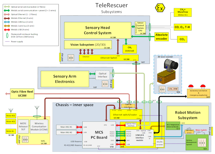
Schema of the main control system (hardware)
The software of the embedded main control system is based on ROS (Robotic Operation System), running on Linux Ubuntu.
The architecture of the control system software is shown in the following figure. The system is logically divided into several parts (ROS nodes). Nodes marked by green are responsible for communication with hardware parts of the robot (motor controllers, sensors etc.); orange nodes are responsible for autonomy behaviour of mobile robot (Autonomy node, Odometry node, 3D mapping node) and 3D map building. Data exchange between subsystems (nodes) is implemented using the standard ROS communication features and is optimised for low latency as the result of some performance tests.
The blue node called Operator Bridge is responsible for communication with the operator control system. This bridge provides a translation of the internal ROS communication to TCP/IP telegrams accepted by the operator station software (the operator station is running under Microsoft Windows and is programmed in C#; it is not based on ROS).
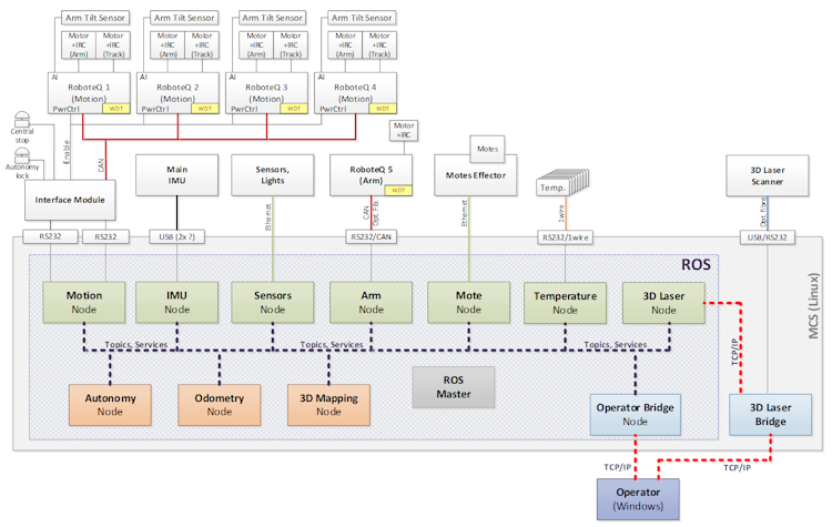
Schema of the main control system (software)
A very important part of the mobile robot is the sensory head located on the top of the sensory arm. The sensory head is a cylindrical module with a flameproof enclosure. Communication with this module is done only via Ethernet.
The sensory head contains five cameras (two for 3D vision, one with a wide field of view for site surveys, one for rear vision and one thermal camera), LED lighting, various gas sensors and an inertial measurement unit (IMU module). The control system for the sensory head is an embedded MCU (Microcontroller Unit) board.
Elevation and rotation of the sensory head and lifting of the additional methane arm are realised by only one BLDC motor with four electromagnetic clutches for selection of the type of movement.
A robust communication system has been designed for communication between the robot and the operator. The main communication line is based on an optical fibre. Since the environment inside a coal mine is hazardous, it is likely that the optical fibre is broken or crushed by the robot. In this situation, a backup wireless communication system is activated. The wireless communication is secured by elements called motes that act as repeaters to achieve hundreds of meters wirelessly.
A simplified drawing of the global network is shown in the following figure. The robot and operator networks are mainly connected by an optical fibre that forms the network 192.168.5.0/24. There are two routers (R1 and R2) at both sides that route packets through the different subnetworks. In total, there are six subnetworks. In order to prioritise the traffic through the wired link, R1 and R2 run a dynamic routeing protocol called Routing Information Protocol version 2 (RIPv2). In case the fibre is broken, all the traffic is directly routed through the wireless ad-hoc network.
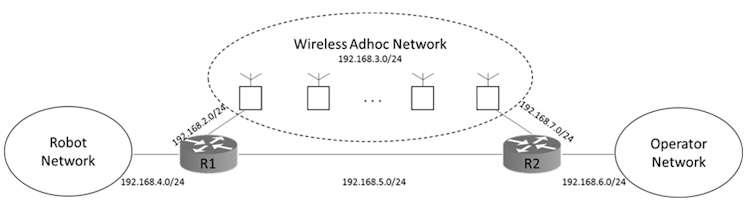
Robot-operator network design
Virtual teleportation is ensured by a specialised operator control panel software. The operator control panel displays all necessary information about the robot and images from camera on a flat monitor; it is also possible to use virtual reality headset to create a "virtual operator station".
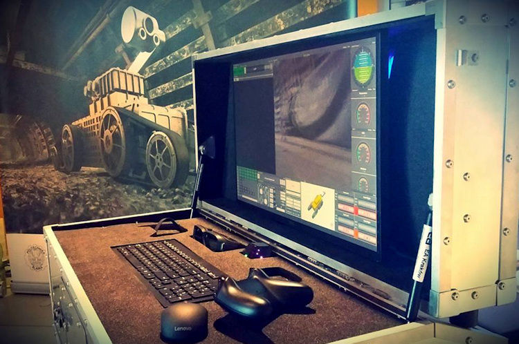
The operator station
The most important task is to meet the safety requirements related to working at a coal mine with the hazard of an explosive atmosphere. There are some limitations related to the ATEX standards (EN 60079-0, Explosive atmospheres – Part 0: Equipment – General requirements).
According to these specifications, at least two independent explosion protections are required. This is realised by several approaches:
The project has been carried out in a framework of an EU programme of the Research fund for Coal and Steel under the grant agreement No. RFCR-CT-2014-00002 and by Polish Ministry for Science and Higher Education from financial sources that constitute the public aid in years 2014-2017 as-signed for an accomplishment of an international co-financed project.
Official TeleRescuer web presentation (www.telerescuer.polsl.pl)